Form Measurement Systems: From Surface to Precision Data
Modern precision manufacturing depends on accurate measurement of component geometry, surfaces, and dimensional characteristics.
Form Measurement Systems help manufacturers evaluate geometric deviations such as roundness, straightness, flatness, cylindricity, contour, and profile with controlled measurement techniques.
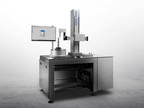
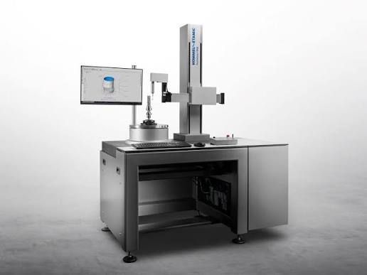
These systems convert physical component surfaces into measurable data that can be analyzed against engineering specifications. Depending on the application, form measurement equipment can use stylus probes, optical sensors, rotary tables, scanning systems, or computer-controlled measurement platforms.
What Are Form Measurement Systems?
Form Measurement Systems are precision metrology systems used to evaluate the geometric shape and form accuracy of manufactured components.
Unlike basic dimensional measurement, form measurement focuses on how closely an actual surface or feature conforms to its intended geometric shape.
Typical measurements include:
- Roundness
- Cylindricity
- Straightness
- Flatness
- Circularity
- Profile
- Contour
- Concentricity
- Runout
- Surface geometry
These measurements are important when small geometric deviations can affect assembly, rotation, sealing, movement, or overall component performance.
From Surface to Precision Data
The measurement process generally follows several stages, beginning with component preparation and ending with analyzed measurement data.
1. Component Preparation
The workpiece is first prepared for measurement.
The component may need to be cleaned to remove dust, oil, chips, or other material that could affect probe contact or optical measurement.
Temperature stabilization may also be important for precision applications because thermal expansion can influence measurement results.
2. Workpiece Positioning
The component is placed on a measurement platform or fixture.
Accurate alignment is important because incorrect positioning can introduce measurement errors or make the selected measurement reference unsuitable.
Depending on the system, the workpiece may be mounted on:
- Precision rotary tables
- Fixtures
- V-blocks
- Magnetic tables
- Specialized component holders
3. Sensor Selection
The measurement system uses a sensor appropriate for the component and measurement characteristic.
Common technologies include:
- Stylus probes
- Optical sensors
- Laser sensors
- Vision systems
- Scanning probes
The sensor must be capable of accessing the feature while providing the required measurement resolution.
4. Surface Scanning
The sensor moves relative to the workpiece and records the surface or geometric feature.
For rotary measurements, the workpiece or measurement head can rotate while the sensor records deviations around the component.
For profile measurement, the probe may follow a contour along a defined path.
5. Data Acquisition
The measurement system converts sensor readings into digital measurement data.
Modern equipment can collect thousands of measurement points during a single scanning operation.
The resulting data provides a detailed representation of the measured feature.
6. Geometric Analysis
Software analyzes the collected data against a defined reference geometry.
The system may calculate parameters such as:
- Form deviation
- Roundness error
- Straightness error
- Flatness deviation
- Profile deviation
- Cylindricity error
- Runout
7. Reporting
The final measurement results can be displayed through numerical values, graphical plots, tolerance comparisons, and inspection reports.
Digital reporting makes it easier to identify trends and compare components across production batches.
Major Types of Form Measurement Systems
Different systems are designed for specific geometric characteristics.
| System Type | Primary Measurement | Typical Application |
|---|---|---|
| Roundness measurement system | Circular form | Bearings, shafts, rings |
| Cylindricity measurement system | Cylindrical form | Precision shafts and bores |
| Contour measurement system | Complex profiles | Mechanical components |
| Surface profile system | Profile geometry | Precision surfaces |
| Straightness measurement system | Linear form | Rails, guides, shafts |
| Flatness measurement system | Planar form | Plates and precision surfaces |
| Optical measurement system | Contactless geometry | Small or delicate components |
Roundness Measurement Systems
Roundness measurement systems evaluate how closely a circular feature matches its ideal circle.
They are commonly used for:
- Bearing components
- Shafts
- Bushings
- Rings
- Cylindrical components
A rotary table or spindle can rotate the component while a sensor measures radial deviations.
The resulting data can identify localized form errors that may not be detected through basic diameter measurements.
Cylindricity Measurement
Cylindricity evaluates the three-dimensional form of a cylindrical surface.
Unlike simple roundness measurement at one cross-section, cylindricity analysis considers the complete cylindrical surface over a defined length.
This can be important for precision shafts, bores, sleeves, and other cylindrical components.
Contour Measurement Systems
Contour measurement systems evaluate complex component profiles.
A stylus or optical sensor follows a defined contour and records changes in geometry.
Applications can include:
- Mechanical profiles
- Sealing surfaces
- Precision grooves
- Mold components
- Automotive components
- Tooling features
Optical Form Measurement
Optical measurement systems use cameras, lasers, structured light, or other non-contact technologies to evaluate component geometry.
These systems can be useful when contact with the surface is undesirable or when components contain delicate or highly finished surfaces.
Advantages can include:
- Non-contact measurement
- High-speed inspection
- Automated data collection
- Measurement of small features
- Digital surface analysis
Stylus-Based Measurement Systems
Stylus systems use a physical probe that follows the component surface.
The probe displacement is converted into measurement data.
Stylus measurement remains useful for many precision form applications because it can provide direct surface tracing and detailed geometric information.
CNC Form Measurement Systems
Computer-controlled systems can automate positioning and measurement sequences.
CNC capabilities may allow the system to:
- Automatically position the probe
- Rotate the workpiece
- Measure multiple features
- Repeat programmed inspection routines
- Apply defined measurement conditions
- Generate automated reports
This can improve consistency for repeated inspection tasks.
Form Measurement vs. Dimensional Measurement
Form measurement and dimensional measurement address different aspects of component accuracy.
| Measurement Type | Main Purpose | Example |
|---|---|---|
| Dimensional measurement | Measure size | Diameter |
| Form measurement | Evaluate geometric shape | Roundness |
| Profile measurement | Evaluate contour | Curved profile |
| Position measurement | Evaluate feature location | Hole position |
| Surface measurement | Evaluate surface characteristics | Roughness |
A component can have the correct nominal diameter while still having excessive roundness or cylindricity deviation.
Key Applications
Automotive Manufacturing
Form measurement can be used for engine, transmission, bearing, shaft, and precision drivetrain components.
Aerospace Manufacturing
Precision form measurement supports inspection of components where complex geometry and tight dimensional requirements are important.
Medical Device Manufacturing
Small and precision components can require detailed geometric inspection.
Bearing Manufacturing
Roundness, cylindricity, raceway profiles, and other geometric characteristics are important for bearing components.
Tool and Die Manufacturing
Contour and profile measurement can verify molds, dies, cutting tools, and other precision tooling.
How to Select Form Measurement Systems
Selecting the appropriate system requires consideration of the component, measurement characteristic, accuracy requirement, and production environment.
Measurement Characteristic
First determine whether the application requires roundness, cylindricity, contour, straightness, flatness, profile, or another measurement.
Component Size
The measurement range must accommodate the diameter, height, length, and overall geometry of the component.
Required Accuracy
The system's resolution, repeatability, probe performance, and calibration characteristics should correspond to the required measurement tolerance.
Sensor Technology
Contact and non-contact sensors have different capabilities and limitations.
Automation Requirements
High-volume production may benefit from CNC positioning, automatic loading, programmed measurement routines, and automated reporting.
Form Measurement Systems Comparison
| Selection Factor | What to Consider |
|---|---|
| Measurement type | Roundness, profile, cylindricity, etc. |
| Sensor | Stylus, optical, laser, vision |
| Measurement range | Component dimensions |
| Resolution | Smallest measurable deviation |
| Repeatability | Consistency between measurements |
| Automation | CNC and automatic inspection |
| Software | Analysis and reporting capabilities |
| Workholding | Fixture and rotary-table compatibility |
| Calibration | Reference standards and verification |
| Data output | Reports and digital inspection records |
Automation and Digital Measurement
Modern Form Measurement Systems increasingly combine sensors, CNC motion, data acquisition, and analytical software.
Automated systems can measure multiple features without manually repositioning the component.
Digital measurement data can also be connected to manufacturing quality systems for process monitoring and traceability.
When measurement results are collected over time, manufacturers can identify trends in machine performance, tooling wear, thermal effects, or process variation.
Calibration and Measurement Accuracy
Accurate form measurement depends on more than sensor resolution.
Important factors include:
- Machine alignment
- Rotary-axis accuracy
- Probe calibration
- Environmental temperature
- Vibration
- Workpiece cleanliness
- Workpiece positioning
- Reference standards
Measurement systems should be calibrated and verified according to established procedures.
Environmental conditions can also matter, particularly when extremely small geometric deviations are being measured.
Maintenance Best Practices
Keep Measurement Surfaces Clean
Dust, chips, oil, and other contamination can affect component positioning and sensor performance.
Check Probe Condition
Stylus tips and other contact components should be inspected for wear or damage.
Verify Rotary Accuracy
Rotary tables and spindles should be checked periodically to maintain measurement consistency.
Maintain Environmental Conditions
Temperature changes and vibration should be controlled where required by the measurement application.
Review Calibration
Regular calibration and verification help maintain confidence in measurement results.
Frequently Asked Questions
What are Form Measurement Systems?
Form Measurement Systems are precision metrology systems used to measure geometric characteristics such as roundness, cylindricity, straightness, flatness, contour, and profile.
What is the difference between dimensional and form measurement?
Dimensional measurement determines the size of a feature, such as diameter, while form measurement evaluates how closely the actual geometry matches its intended shape.
What can a roundness measurement system measure?
A roundness system evaluates deviations of a circular feature from its ideal circular reference, making it useful for shafts, bearings, rings, and other precision components.
Are form measurement systems contact or non-contact?
Both technologies are available. Stylus systems use physical contact, while optical and laser systems can measure selected surfaces without direct contact.
Why is calibration important for form measurement?
Calibration helps verify that the measurement system produces accurate and repeatable results. Machine geometry, sensors, rotary systems, and environmental conditions can all influence measurement accuracy.
Conclusion
Form Measurement Systems transform physical component geometry into precise digital measurement data. By using stylus probes, optical sensors, rotary systems, CNC positioning, and advanced software, these systems can evaluate roundness, cylindricity, contour, straightness, flatness, and other geometric characteristics.
The right system depends on the component geometry, measurement requirement, tolerance, sensor technology, automation level, and production environment. Roundness systems may be appropriate for bearings and shafts, while contour and optical systems can address more complex or delicate surfaces.
Modern form measurement is increasingly connected with automated inspection and digital quality management. CNC positioning, high-resolution sensors, automated analysis, and electronic reporting can help manufacturers monitor geometric accuracy and identify process variation throughout precision manufacturing operations.